Free Body Diagrams: Complete Tutorial with Examples

What is a Free Body Diagram?

A free body diagram (FBD) is a graphical representation used in physics and engineering to visualize the forces acting on a single object. By isolating the object from its surroundings and representing all external forces as vectors, FBDs provide a powerful tool for applying Newton's laws of motion:

Each force vector is drawn with:

  1. Appropriate direction (indicating the force's line of action)
  2. Reasonable relative magnitude (longer arrows for larger forces)
  3. Clear labeling identifying the force type and acting object

The key principle is to include only forces acting ON the object, never forces exerted BY the object on other entities.

Examples of Free Body Diagrams with Detailed Explanations

Example 1: Book resting on a horizontal table

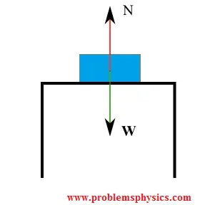
Forces acting on the stationary book:

  1. The gravitational force (weight) \( \vec{W} = m\vec{g} \) exerted by Earth
  2. The normal force \( \vec{N} \) exerted by the table surface, perpendicular to the contact interface

Since the book is in equilibrium (\( \vec{a} = 0 \)), Newton's First Law gives: \[ \sum F_y = N - W = 0 \quad \Rightarrow \quad N = W = mg \] The horizontal forces sum to zero trivially.

Free body diagram of a book on a table showing weight and normal force vectors

Example 2: Block suspended by a rope

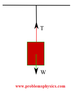
Forces on the stationary suspended block:

  1. Weight \( \vec{W} = m\vec{g} \) (downward, gravitational)
  2. Tension \( \vec{T} \) (upward, along the rope)

Equilibrium condition yields: \[ \sum F_y = T - W = 0 \quad \Rightarrow \quad T = W = mg \] The tension force arises from the rope's molecular bonds resisting stretching.

Free body diagram of a suspended block showing weight and tension force vectors

Example 3: Block pulled horizontally with friction

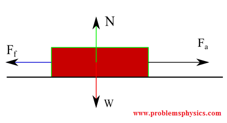
Forces acting on the block (assuming motion or impending motion):

  1. Weight \( \vec{W} \) (downward)
  2. Normal force \( \vec{N} \) (upward, perpendicular to surface)
  3. Applied force \( \vec{F}_a \) (horizontal, direction of pulling)
  4. Kinetic friction \( \vec{f}_f \) (opposing motion, parallel to surface)

The friction magnitude is given by \( f_f = \mu_k N \), where \( \mu_k \) is the kinetic friction coefficient. Vertical equilibrium gives \( N = W \). Horizontally: \[ \sum F_x = F_a - f_f = ma_x \] where \( a_x \) is the block's acceleration.

Free body diagram of a block being pulled showing weight, normal force, applied force, and friction

Example 4: Object in free fall (neglecting air resistance)

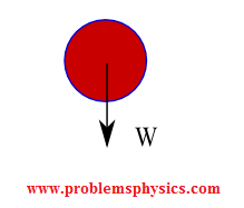
Forces on the falling object:

  1. Weight \( \vec{W} = m\vec{g} \) (downward, only significant force)

Applying Newton's Second Law: \[ \sum F_y = W = mg = ma \quad \Rightarrow \quad a = g \] The object accelerates downward with gravitational acceleration \( g \approx 9.8 \, \text{m/s}^2 \).

Free body diagram of a falling object showing only the weight force vector

Example 5: Box on frictionless inclined plane

Forces acting on the box:

  1. Weight \( \vec{W} = m\vec{g} \) (vertically downward)
  2. Normal force \( \vec{N} \) (perpendicular to the incline)

Resolving weight into components: \[ W_{\parallel} = mg\sin\theta \quad \text{(down the incline)} \] \[ W_{\perp} = mg\cos\theta \quad \text{(into the incline)} \] Since there's no friction, the net force along the incline is \( mg\sin\theta \), causing acceleration: \[ a = g\sin\theta \] Perpendicular to the incline: \( N = mg\cos\theta \).

Free body diagram of a box on a frictionless inclined plane showing weight components and normal force

Example 6: Box on inclined plane with applied force and friction

Forces on the box:

  1. Weight \( \vec{W} = m\vec{g} \)
  2. Normal force \( \vec{N} \)
  3. Applied force \( \vec{F}_a \) (up the incline)
  4. Static friction \( \vec{f}_s \) (direction depends on motion tendency)

If the box is stationary, friction adjusts to satisfy equilibrium: \[ \sum F_{\parallel} = F_a + f_s - mg\sin\theta = 0 \] \[ \sum F_{\perp} = N - mg\cos\theta = 0 \] The maximum static friction is \( f_{s,\text{max}} = \mu_s N \), where \( \mu_s \) is the static friction coefficient.

Free body diagram of a box on an inclined plane with applied force and friction

Example 7: Block suspended by three strings

Diagram of a block suspended by three strings meeting at a point

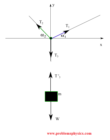
A) Free body diagram for the block (two forces):

  1. Weight \( \vec{W} \)
  2. Tension \( \vec{T}_3' \) from the vertical string

Vertical equilibrium: \( T_3' = W \).

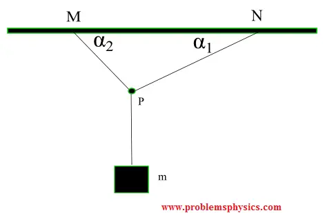
B) Free body diagram for junction point P (three forces):

  1. Tension \( \vec{T}_1 \) (left string)
  2. Tension \( \vec{T}_2 \) (right string)
  3. Tension \( \vec{T}_3 \) (vertical string, equal and opposite to \( T_3' \))

The junction is in equilibrium: \[ \sum F_x = T_{2,x} - T_{1,x} = 0 \] \[ \sum F_y = T_{1,y} + T_{2,y} - T_3 = 0 \] where \( T_3 = W \). This system solves for \( T_1 \) and \( T_2 \) given the angles.

Free body diagrams for the block and junction point in a three-string suspension system

Example 8: Two-block system with inclined plane and pulley

System with two blocks connected by a string over a pulley, one on an incline

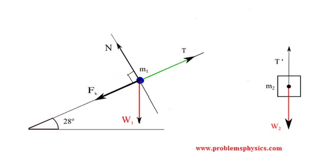
A) Free body diagram for block \( m_1 \) on incline:

  1. Weight \( \vec{W}_1 = m_1\vec{g} \)
  2. Normal force \( \vec{N} \) (perpendicular to incline)
  3. Kinetic friction \( \vec{f}_f \) (opposing motion)
  4. Tension \( \vec{T} \) (up the incline, from the string)

Along the incline (x-direction): \[ \sum F_x = T - f_f - m_1g\sin\theta = m_1a \] Perpendicular to incline: \( N = m_1g\cos\theta \), with \( f_f = \mu_k N \).

B) Free body diagram for hanging block \( m_2 \):

  1. Weight \( \vec{W}_2 = m_2\vec{g} \) (downward)
  2. Tension \( \vec{T}' \) (upward, magnitude \( T' = T \) for massless string)

Vertical equation: \[ \sum F_y = m_2g - T' = m_2a \] assuming downward is positive for \( m_2 \). The two equations combine to solve for acceleration \( a \) and tension \( T \).

Free body diagrams for both blocks in a pulley-incline system